
Motivation
In next week’s neuron transmission lab you will write down a circuit diagram and then implemented it using real circuit components (namely, resistors). As a precursor to the neuron lab we will do the reverse: you will take a real physical circuit, draw its corresponding circuit diagram and solve it, and then verify that your solution agrees with the observed currents and voltages in the real circuit.
Using a breadboard (a device that you stick circuit components into, allowing you to connect and disconnect easily them without soldering) requires a little familiarity with the connection diagram.
The holes in a breadboard are connected according to the color coding below:
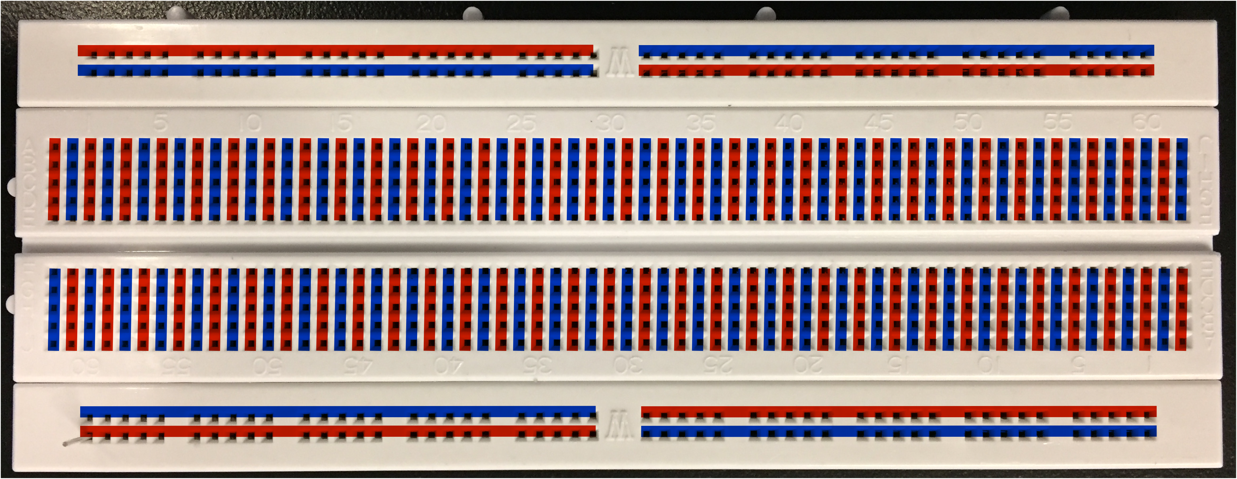
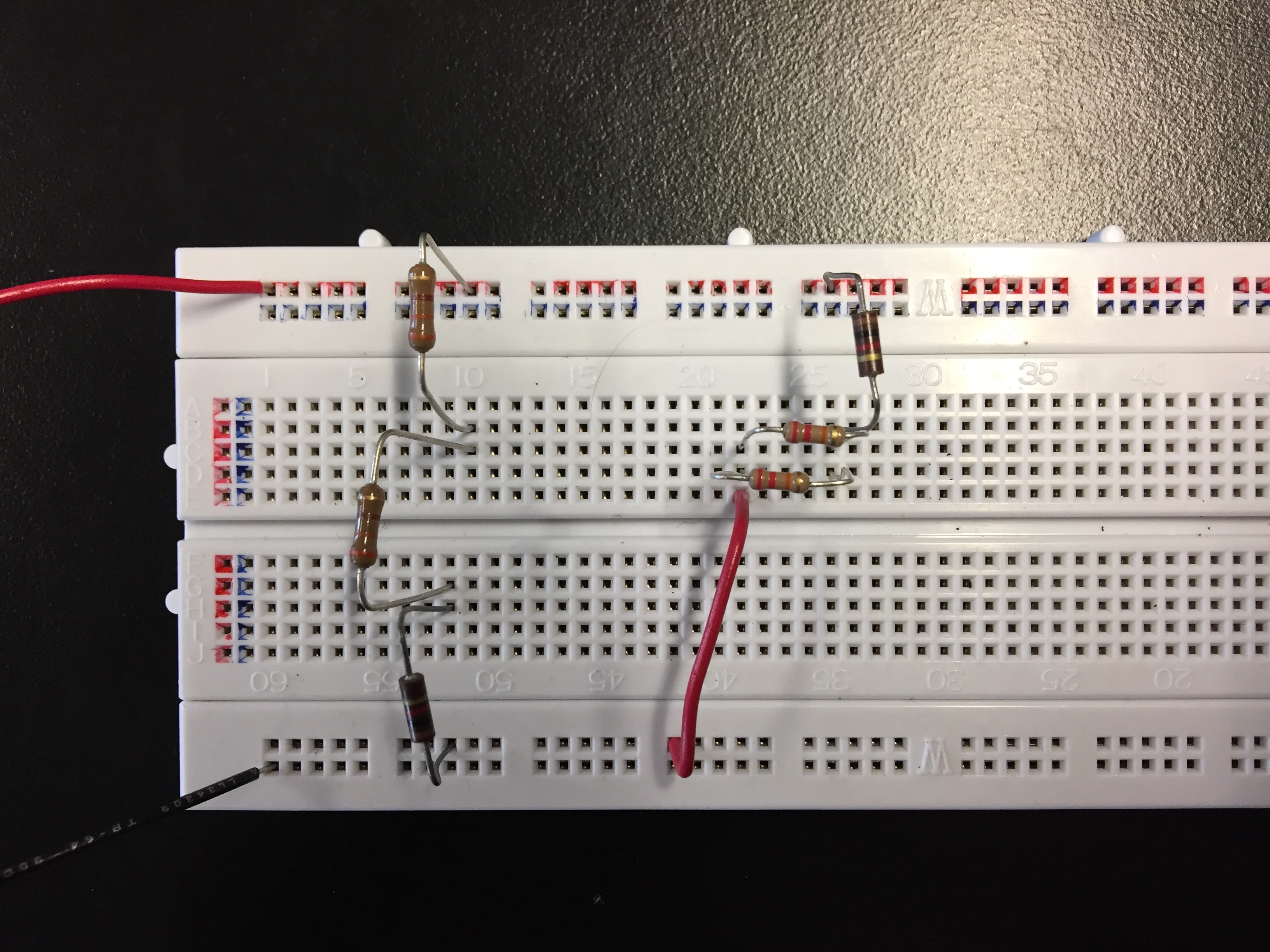
In the center, holes are connected vertically in sets of five. Any wires inserted in any of the five holes are electrically connected (via metallic contacts under the breadboard’s surface). At the top and bottom of the breadboard, holes are connected horizontally in sets of 25. The top and bottom are commonly used to distribute + and – voltage from the battery (or power supply); the center is commonly used to connect together a few components (a resistor or capacitor or two). For instance, in the circuit below the two wires going offscreen bring in the + voltage (at the top) and – voltage (at the bottom) from a power supply.
Set your input voltage
Flip a coin. If it comes up heads, set your voltage supply to 10V. If it comes up tails, set your voltage supply to 20 V.
Circuit diagram
Draw the circuit diagram corresponding to your physical circuit. Arrange the locations of the battery and resistor so that the circuit is easy to understand; this is not usually the same as the physical layout of the circuit. For instance, when resistors are connected in parallel, draw them side by side even if they are not physically oriented that way in the circuit itself. This makes it much easier to understand the function of the circuit.
Label all the parts of the circuit clearly with resistance values in ohms.
Take a picture of your circuit diagram.
Solve your circuit
- Calculate the equivalent resistance of all your resistors.
- Calculate the current you expect to flow through the battery and write it on the circuit diagram.
- Calculate the current you expect to flow through each resistor and write them on the circuit diagram.
- Calculate the expected voltage drop in each resistor and write them on the circuit diagram.
Take a picture of your circuit diagram with all the current and voltage predictions on it. We’re trying to make this a fast and dirty lab, so no need to show any work here: only the final numbers, written on your circuit diagram.
Measure the circuit.
- Temporarily unhook the voltage supply and measure the equivalent resistance using the ohmmeter. Does it agree with your calculation above?
- Measure all the voltage drops across all the resistors and verify that they agree with your calculated values.
- We have been having problems with blown fuses in the multimeters in ammeter mode. Skip the measurements of currents.
Use this blank word document as a template for your work. Keep in mind that this is not a full lab writeup. We only want the answers to the specific questions asked.
Hints
- To measure a current you must put the multimeter in current mode, break the circuit and insert the multimeter in series with the circuit. Ask your TA how to do this if it’s unclear!
- To measure a voltage you must put the multimeter in voltage mode and attach the multimeter in parallel with the circuit. The meter reports the voltage difference dV between its two leads.. Ask your TA how to do this if it’s unclear!
- To measure a resistance you must put multimeter in ohmmeter mode and connect it across the ends of the resistor (or resistors). You will need to remove the resistor from the circuit first. If you don’t isolate the one resistor you are interested in you will probably end up measuring the equivalent resistance of a couple of interconnected resistors. Be sure to remember where the resistor came from so you can re-insert it properly! Take a picture of the circuit before you start dismantling it so you can put it back together correctly.
- If you want to, you can up the resistance value using the code corresponding to the three colored bands on the resistors. Here is a good resource to help with that. (The fourth band, which is typically gold, tells you the manufacturing tolerance of the resistor. We don’t really care about that.)